A heavy inverter is usually mounted on a reinforced wall, steel frame, or dedicated electrical cabinet near the main power distribution area. The location should support the equipment weight while leaving enough space for cooling, wiring, inspection, and maintenance. When engineers install a single phase to 3 phase inverter, they should evaluate the mounting surface and surrounding environment before deciding the final position.
Structural Strength Determines the Basic Location
The first requirement is a stable mounting surface. Heavy inverter equipment should not be fixed to thin partitions, weak panels, or surfaces that may deform under continuous load. Concrete walls, reinforced masonry, and steel support frames are more suitable when the inverter has a larger enclosure or higher installed weight.
Engineers should also inspect the fixing points before installation. Anchor bolts, brackets, and support rails need to match the wall material and equipment weight. The inverter should remain level after mounting because uneven support can place unnecessary stress on the enclosure and mounting hardware.
Vibration is another factor. Pumps, compressors, and other rotating equipment can transfer vibration through walls or structural frames. If the inverter is installed near such machinery, engineers may use a separate support structure or choose another area with lower mechanical disturbance.
For an off grid solar inverter, the mounting area is often close to the battery and DC distribution section. However, engineers should still avoid cramped spaces, excessive heat, moisture, and locations where maintenance access is limited.
Cooling Conditions Affect Long-Term Placement
Inverters generate heat during power conversion, so ventilation has a direct effect on installation layout. Engineers should leave suitable space around air inlets, outlets, fans, or heat dissipation surfaces according to the equipment instructions.
Mounting several units too close together can restrict airflow. Heat from one inverter may also influence neighboring equipment. This becomes more important in electrical rooms where several power conversion devices share the same wall or cabinet.
Direct sunlight and nearby heat sources should also be considered. Outdoor or semi-outdoor installations may experience higher enclosure temperatures during the day. Indoor installations can face similar problems when the inverter is placed beside boilers, furnaces, or poorly ventilated machinery rooms.
When comparing an off-grid solar inverter manufactuer, engineers should review mounting orientation, ventilation requirements, enclosure design, and environmental limitations instead of focusing only on electrical ratings.
Cable Routes Should Stay Short and Accessible
The mounting point should support a clear cable route between the power source, inverter, load, protection devices, and grounding system. Long or complicated cable paths can increase installation difficulty and make future inspection less convenient.
Heavy power cables also require enough bending space. Engineers should avoid positions where cables must make sharp turns immediately after entering the enclosure. DC, AC, communication, and control wiring should be arranged clearly so technicians can identify each circuit during servicing.
For a single phase to 3 phase inverter, engineers may also need to consider the location of motor protection devices, breakers, contactors, and distribution panels. Keeping related electrical equipment within a planned area can simplify cable management and fault checking.
Protection devices should remain visible and reachable. An inverter should not block disconnect switches, circuit breakers, grounding points, or emergency controls. Maintenance personnel need enough working space in front of the equipment to inspect terminals without removing unrelated components.
Parallel Installations Need Additional Planning
Parallel systems require more wall space and more careful cable planning than single-unit installations. Engineers should reserve enough distance between units for ventilation, wiring, communication links, and service access.
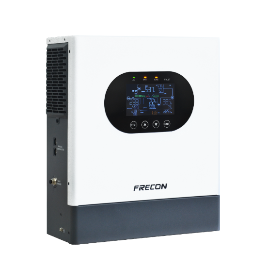
A practical example is the SP200 Solar Hybrid Inverter from FRECON. The unit has dual output terminals and supports a maximum PV input voltage of up to 500 V. It can also support PV feed-in to the grid where local policies permit.
The SP200 supports parallel operation from 1 to 9 units. Three or more units operating in parallel can form a three-phase 380 VAC output. This means engineers should consider future expansion before fixing the first unit to the wall.
If several units may be added later, the original layout should leave space for extra enclosures, cable trunking, protection devices, and communication wiring. Installing the first unit in the center of a limited wall may create problems when the system needs to expand.
For this type of project, FRECON should be assessed in the same way as other equipment suppliers. Engineers should compare the inverter dimensions, mounting requirements, connection method, parallel configuration, and site conditions before preparing the final layout.
Environmental Conditions Also Influence Position
Dust, humidity, dripping water, and corrosive substances can affect electrical equipment. Engineers should avoid mounting an inverter directly below water pipes, near wash-down areas, or in locations where dust regularly accumulates.
Access control can also matter in commercial or industrial sites. Power electronics are usually better placed in electrical rooms, equipment areas, or controlled cabinets rather than in busy passages where the enclosure may be hit by carts or maintenance tools.
An off-grid solar inverter manufactuer may provide installation guidance for environmental limits, but engineers still need to evaluate the actual site. Local temperature, ventilation, wall construction, cable direction, and maintenance procedures can change the suitable mounting position.
Choosing the Right Mounting Approach
A suitable inverter location is not chosen by weight alone. Engineers need to combine structural support, ventilation, cable routing, environmental protection, and maintenance access when planning the installation.
For an off grid solar inverter, staying close to the battery and distribution equipment may reduce cable length, but sufficient clearance and environmental protection remain necessary. Expansion plans should also be considered if more inverter units may be added later.
In practice, engineers usually mount heavy inverter equipment on a reinforced wall, steel frame, or dedicated cabinet close to the electrical distribution area. The final position should support safe wiring, effective cooling, convenient inspection, and possible future expansion.
